-
Ferroic Material, Ferroelectricity:
- Ferroelectricity is a phenomenon which can be observed in a
relatively small class of dielectrics called ferroelectric materials.
In a normal dielectric, upon the application of an electric field,
positive and negative charges will be displaced from their original
position - a concept which is characterized by the dipole moment
or polarization. This polarization, or displacement, will vanish,
however, when the electric field returns back to zero. In a
ferroelectric material, on the other hand, there is a spontaneous
polarization - a displacement which is inherent to the crystal
structure of the material and does not
disappear in the absence of the electric field. In addition, the
direction of this polarization can be reversed or reoriented by applying an
appropriate electric field.
-
Dipole Moment, Polarization:
- The dipole moment, p, for two opposite point charges, is defined as
p=Ql, where Q is the charge magnitude of each point charge and
l is the spatial vector from the negative to the positive point charge.
Applying this concept to a dipole distribution over a volume, polarization is
defined as :
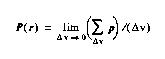 where delta-v is the volume over which the average is taken and r
is the location vector.
where delta-v is the volume over which the average is taken and r
is the location vector.
-
Electric Displacement:
- The electric displacement, D, is related to the polarization
through the linear expression:
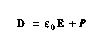 where the derived constant, epsilon, is the permitivity of free space.
-
Polarization Components in FE materials:
- The above equation states that the total charge on the
capacitor is due to the superposition of two sources of charge: e0E, which
is the charge in the absence of dielectric, and P which is the extra
charge introduced by a dielectric between the
electrodes. For linear dielectrics, P is proportional to E, and hence,
the above equation can be simplified and shown as:
 where epsilon is the dielectric permittivity and can be interpreted as the
capacitance of the unit-area, unit-thickness capacitor with dielectric.
where epsilon is the dielectric permittivity and can be interpreted as the
capacitance of the unit-area, unit-thickness capacitor with dielectric.
In FE materials, P is not merely a function of E; it also depends on the
previous history of the material. In other words, the instantaneous voltage
across an FE capacitor does not
provide enough information to determine the capacitor charge. Therefore, it
is not possible to express D as a closed form function of E. However, as
the polarization in FE materials is at
least two or three orders of magnitude larger than e0E, Equation 2-3 can be
approximated by: D=P . This equation implies that the total
surface charge density on a capacitor with FE dielectric
is equal, in magnitude, to the polarization.
Polarization, in ferroelectric materials, can be broken into two fundamental
components, namely; electronic and ionic polarization.
 As their names suggest, electronic and ionic polarizations refer to
the electronic cloud and ionic displacements with electric field,
respectively. Ionic displacement, in turn, can be elastic (non-switching) or
inelastic (switching). If the electric field is removed from the material, each
electron cloud returns to its original position, and so does every ion which
is displaced only slightly (elastic). However, those ions which are displaced
through an inelastic mechanism keep their new positions, even after the
removal of the electric field. In fact, it is these ions
which make ferroelectric polarization much larger than their counterparts in
normal dielectrics. For this reason, non-switching ionic polarization is
also referred to as nonferroelectric ionic polarization.
As their names suggest, electronic and ionic polarizations refer to
the electronic cloud and ionic displacements with electric field,
respectively. Ionic displacement, in turn, can be elastic (non-switching) or
inelastic (switching). If the electric field is removed from the material, each
electron cloud returns to its original position, and so does every ion which
is displaced only slightly (elastic). However, those ions which are displaced
through an inelastic mechanism keep their new positions, even after the
removal of the electric field. In fact, it is these ions
which make ferroelectric polarization much larger than their counterparts in
normal dielectrics. For this reason, non-switching ionic polarization is
also referred to as nonferroelectric ionic polarization.
-
Steady-State Behavior, Hysteresis Loop:
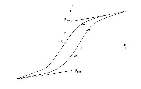
- If a sinusoidal electric field is applied to an FE material, after a
few cycles, polarization will approach its steady-state condition. The plot
of P vs. E, therefore, shows a characteristic pattern known as a hysteresis
loop. A typical hysteresis loop is illustrated here.
-
Saturation Polarization:
- As larger electric fields are applied to an FE material, domains
favorably oriented with respect to the field direction grow at the
expense of other domains. This process continues with increasing electric
field until the least favorably oriented domains switch to the polar
direction most nearly coinciding with the electric field direction. When no
further domain reorientation can occur, the P versus E response usually
becomes linear. If the linear response is extrapolated to the polarization
axis (E=0), the polarization value at the intersection is designated as
the saturation polarization Psat, as shown in the hysteresis loop above.
-
Remanent Polarization:
- The magnitude of polarization at E=0 is called remanent polarization
and it is shown by Pr in the hysteresis loop above. If no domains change
direction while removing the electric field, Pr and Psat
would be the same. However, mechanical boundary conditions normally impose
direction changes in some domains, causing Pr to be less than Psat.
-
Coercive Field:
- The coercive field, Ec, is defined as the horizontal intercept of the
hysteresis loop or the field at which the net polarization becomes zero.
In a single domain crystal, Ec can be interpreted as the field at which
the polarization switches from one state to another. In a multi-domain
crystal, however, Ec will lose its interpretation as there is no single
field at which all domains can switch.
-
Permitivity:
- In linear dielectrics, permittivity is defined as the ratio of electric
displacement to electric field. In FE materials, which are nonlinear, two
types of permittivity can be defined, namely small-signal and
differential permittivity. The former, denoted as epsilon, is
defined as the incremental change in electric displacement per unit electric
field when the magnitude of the measuring field is very small compared
to the coercive electric field.
Macroscopically, epsilon is found by measuring the capacitance. The units of
permittivity are coulombs/volt-meter. The measuring field or voltage must
be kept small to prevent ferroelectric domain reorientation from
contributing to this type of permittivity. In other words, only electronic
and nonswitching polarizations contribute to small signal permittivity.
Differential permittivity is defined as the slope of the hysteresis loop
(electrical displacement versus electric field) at any point.
Note that the differential permittivity is partly affected by the
inelastic polarization and therefore, is different from the
small signal permittivity.
-
Reliability Issues:
- Fatigue refers to the gradual loss of the polarization with
repeated switching or cycling of the material. As an example, a minimum
polarization of 100 fC/mm2 is necessary in a normal DRAM application to
avoid soft errors. It has been shown that the level of available
polarization in PZT moves below this limit after 1012 cycles.
Aging refers to a degradation of polarization parameters (such as the
remanent and the saturation polarizations) with time. A logarithmic decay
of these parameters has been reported in the literature.
Time Dependent Dielectric Breakdown refers to thin film dielectric breakdown
of a ferroelectric capacitor if the voltage stress is applied for a sufficient
period of time (typically more than a month at 3 V). This phenomenon must
be considered in the design of DRAMs using ferroelectric capacitors.
Imprint refers to the tendency of a ferroelectric capacitor to prefer one
state over another if it stays for a long period of time in that state.
Relaxation refers to a reduction of the remanent polarization in
a microsecond time regime if the capacitor is left unaccessed following
a sequence of continuous cycling.