Table of Contents
The audio controller provides a simple interface to the Audio CODEC chip present on the DE2 board. The controller handles the data transmission to and from the chip. The chip configuration is handled by the separate configuration module. The configuration module must be instantiated separately when using the audio controller.
This document will describe the interface and operation of the audio controller and give an overview of the audio data format required to encode the sound waves.
You can download the source code (in Verilog) for the audio controller here.
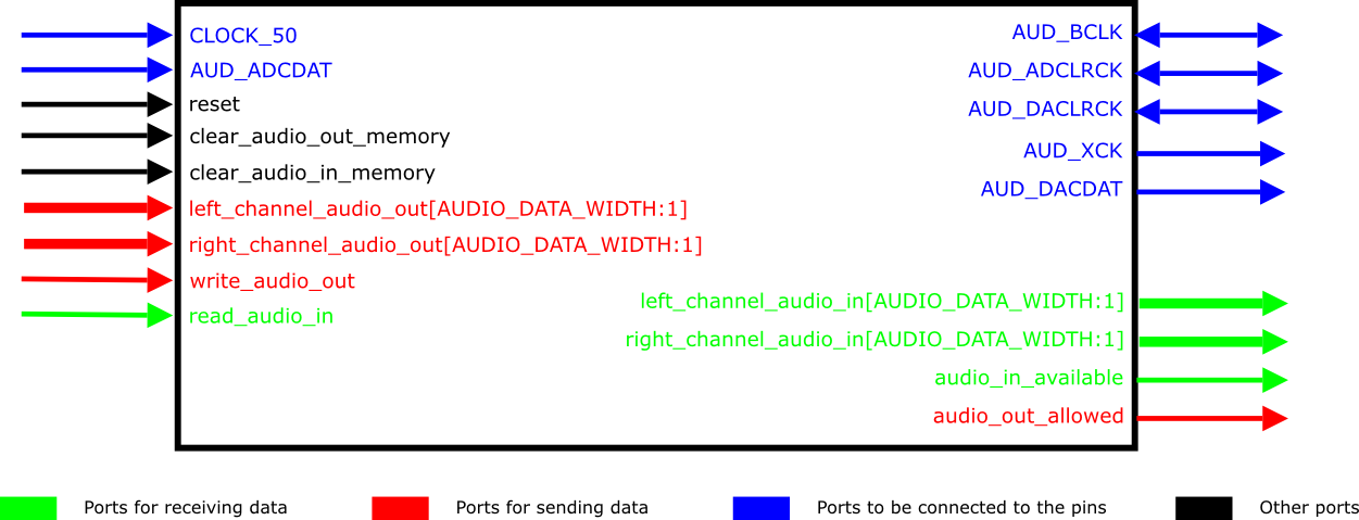
The audio controller interface is illustrated in Figure 1, “Audio controller (by default, AUDIO_DATA_WIDTH is equal to 32)”, with inputs shown on the left, outputs and bidirectional lines on the right. Ports are used as follows:
CLOCK_50- system clock input, must be 50MHz for the timing control to work properly.reset- the active-high reset.AUD_ADCDAT,AUD_DACDAT,AUD_BCLK,AUD_ADCLRCK,AUD_DACLRCK,I2C_SDAT,I2C_SCLKandAUD_XCK- off-chip lines to be connected to the correspondingly named pins, as defined in this file.clear_audio_in_memory- clear the audio input buffer.clear_audio_out_memory- clear the audio output buffer.
Ports for receiving data
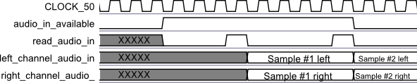
left_channel_audio_inandright_channel_audio_in- Audio data received from the external source.read_audio_in- Read enable signal. The audio input data, if available, will be placed on the data lines on the next clock cycle. This is a level-sensitive signal, which means a new sample of data will be retrieved on every edge, as long asread_audio_inis high.audio_in_available- indicates whether the input data is available or not. Reads will have no effect unless this signal is high.
Ports for sending data
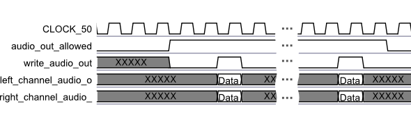
left_channel_audio_outandright_channel_audio_out- Audio data for playback.write_audio_out- enable signal for writing the new data. Level-sensitive, data is written on every clock edge when this signal is high.audio_out_allowed- indicates when the data may be written. Write will have no effect unless this signal is high.
The audio controller is capable of a full-duplex audio input and output. The data ports are 32-bit
wide by default and are connected to the data buffers. The clear_audio_in_memory
and clear_audio_out_memory signals may be used to clear the buffers, and the
audio_in_available and audio_out_allowed signals indicate the
availability of the data (in the case of input) or the free space (in the case of output) in the
buffers. The data itself is a signed integer representing one audio sample. All the signals are
synchronized to the same clock. The interface protocol for sending and receiving data is illustrated
in Figure 2, “Protocol for sending audio data” and Figure 3, “Protocol for receiving audio data”, respectively.
The audio controller consists of two main parts: the input module and the output module. This section will provide a short overview of each.
The audio input and output modules consist of the shift registers connected to the data buffers.
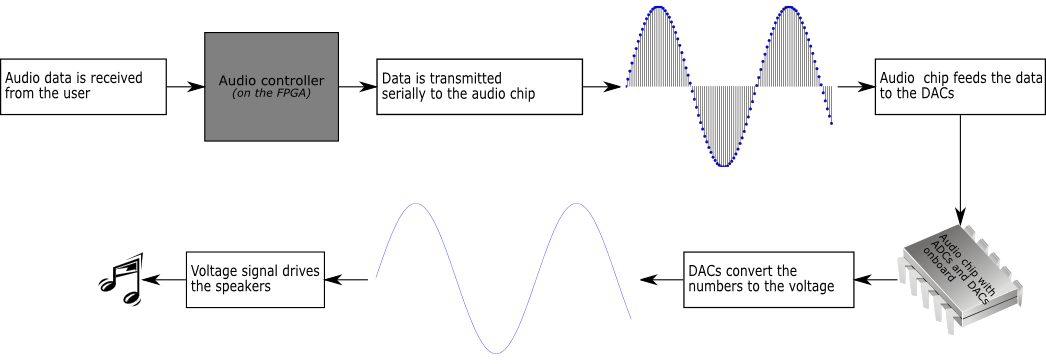
In the case of the audio output, the data received from the user is buffered and then shifted-out to the audio chip at the appropriate rate. The audio chip then feeds this data directly to the DACs.
In the case of the audio input, the process is reversed: the data received from the audio chip is shifted-in and placed in the data buffers. The data comes directly from the ADCs on-board the audio chip.
The audio controller uses the raw PCM data streams, both for the input and for the output. The PCM data stream is essentially a sequence of numbers representing the intensity of the signal at a given moment. Each of these numbers is called a sample. The sound may be represented (i.e., sampled) by a sequence of the samples. This sequence has a frequency associated with it, which tells the rate at which the original signal was sampled. This sampling rate is necessary for the correct signal reconstruction.
For the audio controller the default sampling rate is 48kHz with a default sample size of 32 bits. Furthermore, there are 2 channels both for the input and for the output. The sampling rate and sample size may be changed at configuration time if necessary. The audio samples are presented as the 2's-complement signed integers.
For the audio playback, the PCM data is fed directly to the DACs, which convert the value to a voltage. This analog voltage output is connected to the Line-out jack on the DE2 board which can then drive the headphones or the speakers. This process is illustrated in Figure 4, “Digital to analog audio conversion process”.
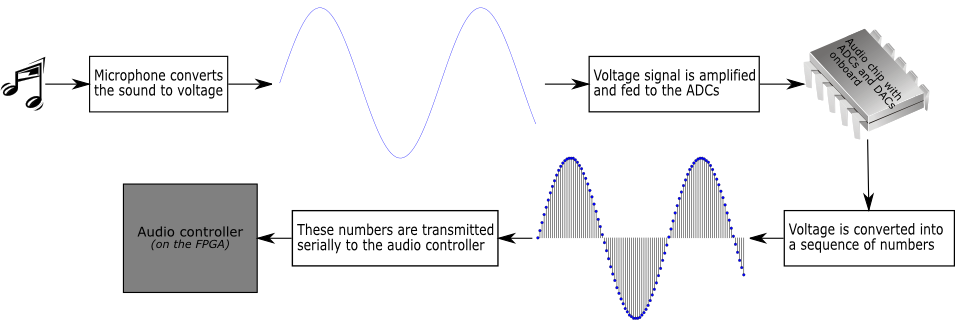
For the audio input (or recording), the process is reversed. You can have either the microphone connected to the Mic jack on the DE2 board, or some other device connected to the Line-in jack (but not both at the same time). These jacks are connected to the inputs of the ADCs, which convert the voltage to the digital value. This value is then transmitted to the audio controller. This process is illustrated in Figure 5, “Analog to digital audio conversion process”.
The sample circuit using the audio controller is available here. You are provided with the full Quartus project and the .sof file already compiled and ready to be programmed.
The purpose of the circuit is very simple. Its main function is to generate a few different frequency signals and play them using the audio controller. The signal frequency is selected with the switches 0 to 3 on the DE2 board. Upon connecting the Line-out output to the speakers, you should be able to hear the sounds with a few different frequencies, depending on how the switches are set. When all four switches are off, there is no sound generated.
The secondary function of the circuit is to superimpose the microphone input on the generated signal. If you connect the microphone to the Mic jack, you should be able to hear the sound from the microphone superimposed on the signal that the circuit is generating.