Table of Contents
The PS/2 controller can be used to communicate both with a PS/2 keyboard and a PS/2 mouse. It provides an interface to the PS/2 protocol, handling the data transmission, error detection and the timing control.
The PS/2 controller interface consists of the PS/2 clock and the PS/2 data inputs, and two 8-bit data ports. One of the 8-bit data ports is used for sending commands to the PS/2 device (mouse or keyboard), the other is for receiving data from the PS/2 device. There are also control signals provided to indicate the arrival of a new command from the PS/2 device and the status of the command transmission to the PS/2 device. The timing control necessary for the PS/2 communication is handled by the controller.
This document will describe the interface and operation of the PS/2 controller and give an overview of the PS/2 protocol.
You can download the source code (in Verilog) for the PS/2 controller here.
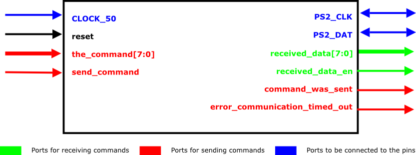
The PS/2 controller interface is illustrated in Figure 1, “PS/2 Controller”, with inputs shown on the left, outputs on the right, and PS2_CLK and PS2_DAT lines being bidirectional. The blue lines are to be connected to the corresponding pins on the DE2 board, the green lines are used for receiving commands, and the red lines are used for sending commands. The red lines might be left unconnected if the user does not need to send the data to the PS/2 device. Ports are used as follows:
Ports that must be connected:
CLOCK_50- system clock input, must be 50MHz for the timing control to work properly.reset- the active-high reset.PS2_CLKandPS2_DAT- PS2 clock and data lines, respectively. These lines should be connected to the correspondingly named pins on the DE2 board, as defined in this file.received_data- last data received from the PS/2 bus. 8 bit word.received_data_en- new data signal. It is driven high for one clock cycle whenever a new data is received (i.e.,received_datachanges).
Optional ports:
the_command- command to be sent, 8 bit input. Has to be valid on the same positive edge as when thesend_commandsignal is first asserted.send_command- command ready signal, should be driven high for at least one clock cycle to start the transmission. This signal may be held high during the transmission, in which case the controller will wait for the signal to be de-asserted before entering the idle state (i.e., getting ready for another command). The transmission status signals (listed below) also hold their value from the current transmission until thesend_commandsignal is de-asserted.command_was_sent- this signal is driven high once the command is successfully sent.error_communication_timed_out- indicates the transmission error when sending the command.
INITIALIZE_MOUSE- if set to one, the controller will assume that the mouse is connected to the PS/2 port and initialize it to the streaming mode. The initialization circuitry just enables the data reporting as described in the section called “PS/2 Mouse protocol” and then relinquishes the command out lines back to the user. The initialization is done every time the controller is reset.
The controller interface consists of two parts: command-in and command-out. If using the optional command lines to send commands to the PS2/device, the command output will always take a precedence over the command input.
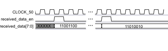
The commands are received automatically, and the most recent command is stored in the register
connected to the received_data port. The signal
received_data_en is driven high for one clock cycle whenever a new command is
received. The protocol timing is illustrated in Figure 2, “Timing diagram for receiving commands”.
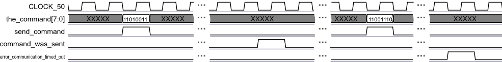
PS/2 commands may be sent using the four command-out ports: the_command,
send_command, command_was_sent, and
error_communication_timed_out. Once the_command lines have
been set to the desired value, the send_command line is driven high, and the
command transmission commences. The send_command line has to be kept high for at
least one clock cycle. After the command transmission is complete. either the
command_was_sent or the error_communication_timed_out signal
is activated, which indicate a transmission success or failure, respectively. These status signals are
held until either the send_command line is de-asserted, or for one clock cycle,
whichever is less. The protocol timing is illustrated in Figure 3, “Timing diagram for sending commands”.
The PS/2 keyboard communicates through the bi-directional half-duplex line. When the line is idle, the keyboard may send the data consisting of 8 bit words and representing the key codes. Additionally, there is a set of commands that may be exchanged between the host and the keyboard. The host has priority over the communication line (i.e., command may be sent at any time and there will be no key codes transmitted until the command finishes).
Although the keyboard will operate properly without any configuration, the user may wish to change certain parameters (e.g., instruct the keyboard to turn on/off the status LEDs or change the key repeat rate). This can be performed by sending the appropriate command to the keyboard, as described in the section called “Host-to-Keyboard communication”.
The keyboard will send a code consisting of one or more 8 bit words whenever the key is pressed, held down, or released.
The codes for the conventional keyboard are listed in Appendix A, List of key codes. "Make" code is sent when the key is pressed down, and repeated periodically
if the key is held down. The "break" code is sent when the key is released. The codes will appear on the received_data
port of the PS/2 controller as they are received. It is the user's responsibility to check the code before it is overwritten.
In addition to the key codes, the keyboard might also send commands to the host. The most common commands are listed in Table 1, “Keyboard-to-host commands”.
Table 1. Keyboard-to-host commands
| Code (hexadecimal) | Command |
|---|---|
| FA | Acknowledge |
| AA | Self Test Passed |
| EE | Echo response |
| FE | Resend request |
| 00 | Error |
| FF | Error |
The host may send the commands to the keyboard to control its behavior. The most common commands are described in Table 2, “Host-to-keyboard commands”, and you may refer to [ce] for an exhaustive list.
Command transmission takes precedence over the data transmission from the keyboard, and will inhibit the transmission of any key codes. Instead, the keyboard will transmit an acknowledge code upon receiving the command. The PS/2 controller provides a simple interface to send the commands, as described in the section called “Interface description”.
Table 2. Host-to-keyboard commands
| Code (hexadecimal) | Command |
|---|---|
| ED | Set status LEDs - This command can be used to turn on and off the Num Lock, Caps Lock and Scroll Lock LEDs. After receiving this command, the keyboard will reply with an ACK (FA) and wait for another byte which determines the status of the LEDs. Bit 0 controls the Scroll Lock, bit 1 controls the Num Lock and Bit 2 controls the Caps lock. Bits 3 to 7 are ignored. |
| EE | Echo - The keyboard should reply with an Echo (EE) upon receiving this command. |
| F0 | Set scan code set - Upon receiving F0, the keyboard will reply with an ACK (FA) and wait for another byte. This byte can be in the range 01 to 03, and it determines the scan code set to be used. Sending 00 as the second byte will return the scan code set currently in use. |
| F3 | Set repeat rate - The keyboard will acknowledge the command with an ACK (FA) and wait for the second byte which determines the repeat rate. Refer to [ce] for more information. |
| F4 | Keyboard Enable - Clears the output buffer, enables the keyboard (i.e., key codes will be transmitted) and returns an ACK. |
| F5 | Keyboard Disable - Resets the keyboard, disables the keyboard (key codes will not be transmitted) and returns an ACK. |
| FE | Resend - Upon receipt of the resend command the keyboard will retransmit the last byte sent. |
| FF | Reset - Resets the keyboard. |
The PS/2 mouse operates in the similar manner as the PS/2 keyboard, except the data packets are different. The mouse sends the data using 3 byte packets. Every packet consists of the relative movement since the last transmission and the button state. Additionally, there is a set of commands that the host may send to the mouse to control its operating modes.
This document describes the basic features of the mouse protocol. These features are sufficient for the most common uses of the mouse, but should you need an exhaustive listing, refer to [ce].
After power-on, or the reset command, the mouse will enter the reset mode, where it will perform the self-test, report the success or failure, and then transmit the device ID, which is always zero. After the self-test, the operating parameters will be set as described in Table 3, “Default parameters”.
Table 3. Default parameters
| Name | Value |
|---|---|
| Sampling rate | 100 samples/s |
| Resolution | 4 counts/mm |
| Data reporting | disabled |
By default, the mouse enters the streaming mode after reset. In this mode, the mouse will send the movement packets whenever it detects a movement or the change in button state. However, please note that the data will not be sent by the mouse by default. You must enable the reporting by sending the "Enable Data Reporting" command as described in Table 6, “Host-to-mouse commands”. Although there are other operating modes present in the protocol, streaming mode is the most useful and is the only mode discussed in this document.
When in the streaming mode of operation, mouse will periodically send the data packets containing the following information:
Button state - 3 bits representing the state of the left, right and middle buttons.
Relative position - two 9-bit 2's-complement numbers representing the amount of movement that has occurred since the last transmission
Data packet format is illustrated in Table 4, “Mouse data packet”.
Table 4. Mouse data packet
| Bit 7 | Bit 6 | Bit 5 | Bit 4 | Bit 3 | Bit 2 | Bit 1 | Bit 0 | |
|---|---|---|---|---|---|---|---|---|
| Byte 0 | Y overflow | X overflow | Y sign | X sign | Always 1 | Middle button | Right button | Left button |
| Byte 1 | X movement | |||||||
| Byte 2 | Y movement | |||||||
The mouse has two internal counters to keep track of the relative position. The counters are incremented/decremented every time the mouse is moved. The counter step with respect to the physical distance depends on the resolution (which can be changed as described in [ce]), with the default being 4 counts/mm. The counters are reset every time the position data is transmitted to the host.
In addition to the data packets, the mouse may also send the commands described in Table 5, “Mouse-to-host commands”.
Table 5. Mouse-to-host commands
| Code (hexadecimal) | Command |
|---|---|
| FA | Acknowledge |
| AA | Self Test Passed |
| FC | Self Test Failed |
| 00 | Device ID. Sent immediately after the self test status command and is always 0x00 |
The host may send the commands to the mouse to control its operating modes and other parameters. The most useful commands are described in Table 6, “Host-to-mouse commands”. If the mouse is in streaming mode, the host should disable the data reporting prior to sending any other commands. The mouse will acknowledge every command.
Table 6. Host-to-mouse commands
| Code (hexadecimal) | Command |
|---|---|
| FF | Reset |
| F6 | Reset without self-test |
| FE | Resend the last byte |
| F4 | Enable data reporting - the mouse will start transmitting the movement packets |
| F5 | Disable data reporting - the mouse will stop transmitting the movement packets |
You can find an example design using the PS/2 controller here. This is the ready to use Quartus project. The .sof file is also included.
The operation of the circuit is very simple - the received_data port of the PS/2 controller is connected to the two
HEX displays through a decoder, so that you can see the hexadecimal 8 bit value of the code. Whenever some data is received, it is displayed on the HEX display,
and stays there until the next word of data is received. For example, if you connect the PS/2 keyboard to the controller, the key codes will be displayed
as you press the keys.
[ce] PS/2 physical protocol and interface. http://www.computer-engineering.org/.
[bl] Interfacing the PC's keyboard. http://www.beyondlogic.org/keyboard/keybrd.htm.
A. List of key codes
Key names are on top, with the hexadecimal make code below.
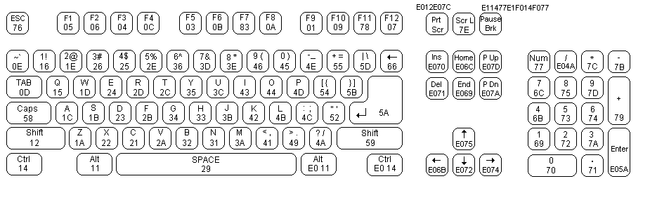
Table A.1. Standard PS/2 Keycodes, default set (set 2)
| KEY | MAKE | BREAK | KEY | MAKE | BREAK |
|---|---|---|---|---|---|
| A | 1C | F0,1C | R ALT | E0,11 | E0,F0,11 |
| B | 32 | F0,32 | APPS | E0,2F | E0,F0,2F |
| C | 21 | F0,21 | ENTER | 5A | F0,5A |
| D | 23 | F0,23 | ESC | 76 | F0,76 |
| E | 24 | F0,24 | F1 | 05 | F0,05 |
| F | 2B | F0,2B | F2 | 06 | F0,06 |
| G | 34 | F0,34 | F3 | 04 | F0,04 |
| H | 33 | F0,33 | F4 | 0C | F0,0C |
| I | 43 | F0,43 | F5 | 03 | F0,03 |
| J | 3B | F0,3B | F6 | 0B | F0,0B |
| K | 42 | F0,42 | F7 | 83 | F0,83 |
| L | 4B | F0,4B | F8 | 0A | F0,0A |
| M | 3A | F0,3A | F9 | 01 | F0,01 |
| N | 31 | F0,31 | F10 | 09 | F0,09 |
| O | 44 | F0,44 | F11 | 78 | F0,78 |
| P | 4D | F0,4D | F12 | 07 | F0,07 |
| Q | 15 | F0,15 | SCROLL | 7E | F0,7E |
| R | 2D | F0,2D | [ | 54 | FO,54 |
| S | 1B | F0,1B | INSERT | E0,70 | E0,F0,70 |
| T | 2C | F0,2C | HOME | E0,6C | E0,F0,6C |
| U | 3C | F0,3C | PG UP | E0,7D | E0,F0,7D |
| V | 2A | F0,2A | DELETE | E0,71 | E0,F0,71 |
| W | 1D | F0,1D | END | E0,69 | E0,F0,69 |
| X | 22 | F0,22 | PG DN | E0,7A | E0,F0,7A |
| Y | 35 | F0,35 | UP | E0,75 | E0,F0,75 |
| Z | 1A | F0,1A | LEFT | E0,6B | E0,F0,6B |
| 0 | 45 | F0,45 | DOWN | E0,72 | E0,F0,72 |
| 1 | 16 | F0,16 | RIGHT | E0,74 | E0,F0,74 |
| 2 | 1E | F0,1E | NUM | 77 | F0,77 |
| 3 | 26 | F0,26 | KP / | E0,4A | E0,F0,4A |
| 4 | 25 | F0,25 | KP * | 7C | F0,7C |
| 5 | 2E | F0,2E | KP - | 7B | F0,7B |
| 6 | 36 | F0,36 | KP + | 79 | F0,79 |
| 7 | 3D | F0,3D | KP EN | E0,5A | E0,F0,5A |
| 8 | 3E | F0,3E | KP . | 71 | F0,71 |
| 9 | 46 | F0,46 | KP 0 | 70 | F0,70 |
| ` | 0E | F0,0E | KP 1 | 69 | F0,69 |
| - | 4E | F0,4E | KP 2 | 72 | F0,72 |
| = | 55 | FO,55 | KP 3 | 7A | F0,7A |
| \ | 5D | F0,5D | KP 4 | 6B | F0,6B |
| BKSP | 66 | F0,66 | KP 5 | 73 | F0,73 |
| SPACE | 29 | F0,29 | KP 6 | 74 | F0,74 |
| TAB | 0D | F0,0D | KP 7 | 6C | F0,6C |
| CAPS | 58 | F0,58 | KP 8 | 75 | F0,75 |
| L SHFT | 12 | FO,12 | KP 9 | 7D | F0,7D |
| L CTRL | 14 | FO,14 | ] | 5B | F0,5B |
| L GUI | E0,1F | E0,F0,1F | ; | 4C | F0,4C |
| L ALT | 11 | F0,11 | ' | 52 | F0,52 |
| R SHFT | 59 | F0,59 | , | 41 | F0,41 |
| R CTRL | E0,14 | E0,F0,14 | . | 49 | F0,49 |
| R GUI | E0,27 | E0,F0,27 | / | 4A | F0,4A |