| Main | Assembly Programming | Input/Output | Memory | Computer Architecture | Advanced Topics |
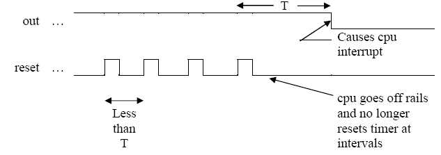
A simple microprocessor is to have a watchdog timer installed. This timer will interrupt the processor unless it is constantly reset by the processor which it would normally do. This interrupt would happen if the processor went ‘off the rails’ because of a software problem, a power spike or something like that.
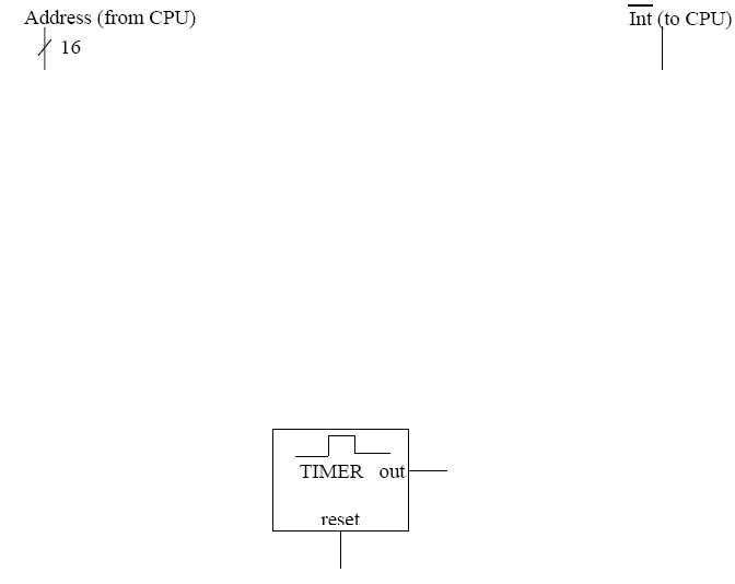
A circuit diagram is started below. The timer in the diagram gives a single positivegoing pulse which can be extended by ‘retriggering’ using the reset line. Some information about the timer and use are given on the diagrams.
The interrupt line is shared by other devices and is active when low.
In the scheme to be used, the processor will reset the timer (and thus avoid the interrupt) by accessing a specific address, $FFE0, faster than the pulse time of the timer, thus restarting the pulse without an interrupt being generated.
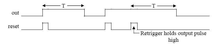
Timer: Relationship between reset input and the output:
T = pulse time
Use of watchdog:
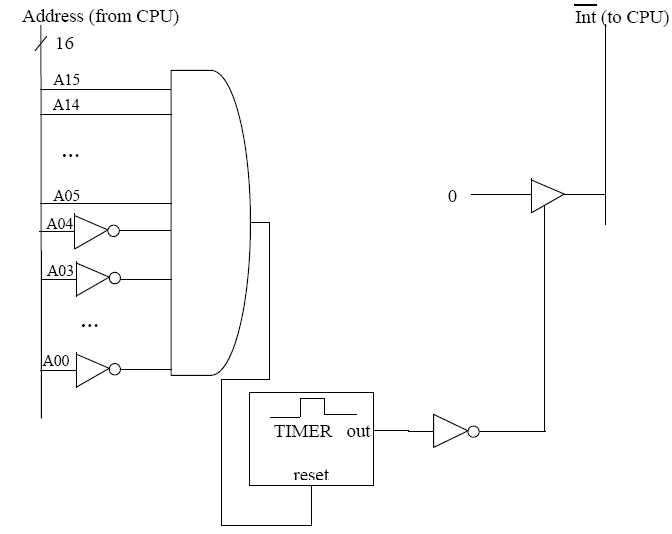
Attach the timer to the 16-bit address bus and to the interrupt line so it will respond as required using supporting logic. For full marks, use ands /ors / nots and other gate-level devices only.