Bitwise
Instructions (shifts, AND, rotates, etc.)
Andreas Moshovos, Jan 2024
So far, we have mostly used instructions that move data around or treat the contents as values. Some examples below:
movi r9, 10 # write the number 10
into register r9. 10 is represented in binary form and in 32b eventually. It
comes as a 16b constant in the instruction and is sign-extended into r9
add r9, r8, r0 # effectively copy
the value from r8 into r9
add r9, r8, r10 # add the values in
r8 and r10 and write their sum into r9
stw r9, 16(r8) # store the value in
r9 into memory starting at the address calculated by taking the value in r8 and
adding 16 to it. Four bytes are written in little-endian order
ldw r9, 32(r8) # read for bytes
from memory starting from the address calculated by taking the value in r8 and
adding 32 to it. The bytes go in little-endian order into r9.
movhi r8, 0x1234 # write the 16b
number 0x1234 into the upper 16b of register r8 while zeroing out the 16 least
significant bits of r8
beq r9, r8, somewhere # compare r9
and r8 (their values) if there are equal PC becomes the address corresponding
to the label somewhere, otherwise PC =PC+4
Here we will be discussing another set of instructions that tread the values in registers as a collection of 32 individual bits. These include instructions that perform bitwise logical operations such as AND, OR, EOR (exclusive OR) and shifts and rotates.
Bitwise
logical operations
The AND instruction:
Let’s use the and instruction as a representative example of what these instructions do:
and r8, r9, r10
You can probably guess what this instruction does. Let’s look at a few example inputs (writing the values in binary form will help):
|
INPUTS |
OUTPUT |
|
|
R9 |
R10 |
R8 |
|
0xFFFFFFFF (all ones) |
0x12345678 |
0x12345678 |
|
0xF0F0F0F0 (every other 4b is all ones) |
0xfedcba98 |
0xf0d0b090 |
|
0x11337777 |
0x2345678 |
0x00305670 |
This instruction treats the register values as 32 element vectors where every element is a bit. The rightmost is bit #0 whereas the leftmost is bit #31. So, there are 32 such bits in the first source operand r9, and 32 in the second source operand r10. It then performs a the logical AND operation across the corresponding bits of these two operands. That is, bit #0 of the output register r8 will be the result of ANDing bit #0 of register r9 and bit #0 or register r10, bit #1 of r8 will be the AND of bit #1 of r9 and bit #1 of r10, and so on, up to bit #31:

Here’s another example showing example values for r9 and r10 and the result in r8:
• and r8, r9, r10
•
R9 = 0001 0001 0010 0010 0000 0111 0000 1111
•
R10 =
0111 0110 0010 1000 0011 0011 0100 0100
•
R8 = 0001 0000 0010 0000 0000 0011 0000 0100
The OR, XOR, and NOR Instructions:
Besides AND, NIOS II also has OR, XOR, and NOR instructions all performing the corresponding bit-wise functions. AND, OR, XOR and NOR, as you might recall from Boolean algebra/digital design are two input Boolean functions producing a single bit output. The following table reviews them:
|
INPUTS |
AND |
OR |
XOR |
NOR |
|
|
0 |
0 |
0 |
0 |
0 |
1 |
|
0 |
1 |
0 |
1 |
1 |
0 |
|
1 |
0 |
0 |
1 |
1 |
0 |
|
1 |
1 |
1 |
1 |
0 |
0 |
Immediate Variants
In addition to the aforementioned instructions that accept two registers as input, there are variants where the second input operand is a 16b immediate. This is similar to the ADD vs. ADDI we have already seen. Natively, NIOS II implements ANDI, XORI and ORI. Both zero-extend the immediate argument. For example, is r9=0xffffff then we have the following:
·
andi r8,
r9, 0x5555 à r8=0x00005555
· xori r8, r9,
0x5432 à r8=0xffffabcd
· ori r8, r9,
0x5432 à r8=0xfffffff
Finally, there are also ANDHI, XORHI, and ORHI where the immediate argument corresponds to bits 31 to 16 (instead of bits 15 to 0). For example, lets’ assume r9=0xF0F00F0F:
·
andhi
r8, r9, 0xFFFF à r8=0xF0F00000
·
xorhi
r8, r9, 0xFFFF à r8=0x0F0F0F0F
·
orhi r8,
r9, 0xFFFF à r8=0xFFFF0F0F
Shift and
Rotate Instructions
The next set of instructions treat the bits of a register as being in a chain, one connected to its two neighbors. That is bit #3 is chained to bit #4 on its left, and bit #2 on its right:
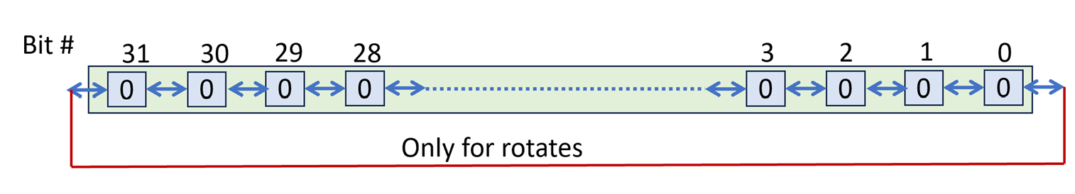
The instructions “push” the bits either to the left or to the right changing their position within the “chain”. Shifts treat the register as having open ends: bits that are shifted out are discarded and vacant positions are filled in with proper values (more on this shortly). Rorates assume there is a chain connection between bits #31 and #0 so, no bit is pushed out.
All instructions take the following form:
OPERATION Rdest, Rsource, X
Where X can be either a register or an immediate.
They take the value in Rsource (e.g., r8) and move it left or right (counter-clockwise, or clockwise) by as many bit positions as given by the value or argument X.
Let’s first look at rotates.
Rotate Instructions
NIOS II implements the rotate left instructions ROL and ROLI. For example, assume that r9=0x12345678 and that r10=0x4 then we have:
· rol r8, r9, r10 à r8 – 0x23456781
· roli r8, r9, 8 à r8 = 0x34567812
Both instructions rotate the value taken from the first input operand (r9 in our examples) by as many bits indicated by the second source operand (either a register or an immediate) clockwise, meaning towards the left. They rotate because these instructions treat the register a cycle with bits #31 and #0 being next to each other (red line in the above diagram). Only the last 5 bits of the second operand are relevant. Why? Because there are only 32 bits in the cycle. So, rotating by 33 is the same as rotating by 1.
For rotate right, NIOS II implements on the register version, ror:
· ror r8, r9, r10 à r8= 0x81234567
Why no rori? Think whether we can get the same effect with roli instead? If we wanted to shift right say by 6 bits, can we get the same effect by shifting left instead by some other number of bits?
Shift Instructions
These tread the value as one having a chain with open ends left of bit #31 and right of bit #0. All are of the form:
OPERATION Rdest, Rsource, X
Where Rdest and Rsource are registers and X can be a register or an immediate.
The shift left instructions take a value from a register and shift it by N bit positions to the left as specified by the third argument X. Since shifting left will leave N vacant positions on the left side of the register (least significant N bits) those are filled with 0s. For example, assume r9=0x12345678 and r10=0x12, then:
·
sll r8, r9, r10 à r8 = 0x45678000
·
slli r8, r9, 4 à r8 = 0x23456780
SLL stands for Shift Logical Left. I am not sure I like the name “logical” here as it may create confusion later one when we refer to the shift right operations. In any case, that’s what they are called and as long as we understand what they do we can use them.
Please note that shift left by 1 bit is equivalent to multiplying the input value by 2. This applies to all bit patterns whether we intend to interpret them as signed or unsigned. For example, consider 0000..11(2) (meaning binary). Shifting left by 1 this becomes 00..0110(2). The original number was 3 and the shifted one is 3x2=6. Similarly, 11…1(2) is -1 in 2’s complement and shifted left by 1 becomes 1…10(2) which is -2. Do keep in mind that we have limited number of bits (always 32) and so our arithmetic is also of limited precision. So, it is possible for very large positive number or very small negative numbers to get overflow or underflow (meaning the result will be cropped to 32bits and will not be the original number multiplied by 2x, try 10…0 and 01…1 as examples and treat them as signed).
In general shifting left by N bits amounts to multiplying the input number (if we wish to treat it as a number) by 2^N. This should be familiar to you from the decimal system where shifting by one digit to the left amounts to multiplying by 10, e.g., 0123 becomes 1230.
Now let’s discuss rotate right instructions. Besides the register and immediate variants there is one more option. Whether the shift is “logical” or “arithmetic”. When we are shifting right, we will end up with several vacant bit positions at the most significant bits. The question is what to fill these with. To appreciate the naming and the functionality it is relevant to start from asking what we want the input value to be considered at: as a collection of bits or as a signed number. The “logical” shift right instructions fill the vacant positions with zeros whereas the “arithmetic” shift right instructions fill them with the inputs MSb (bit #31). The logical shift instructions treat the input as an *unsigned* number (equivalent to a collection of bits without sign), whereas the arithmetic ones treat it as a signed number. In either case, the instructions have the effect of diving the input number by a power of 2. Shifting by 1 bit to the right is equivalent to dividing 2 and shifting right by N positions to the right is equivalent to dividing by 2^N. There is one exception which is shifting right arithmetic where the input Rsource contains -1. In that case, no matter how many bits we shift it by, since the sign is replicated the result will always be all 1s which is -1 :(
Examples, below. Assume that r9=x87654321 and r7=0x12345678, and r10 = 0x4 (pay attention to what bit #31 is in Rsource):
·
srl r8, r9, r10 à r8=0x08765432
·
sra r8, r8, r10 à r8=0xF8765432
·
srli r8, r9, 16 à r8=0x00876543
·
srai r8, r9, 16 à r8=0xFF876543
·
srl r8, r7, r10 à r8=0x01234567
·
sra r8, r7, r10 à r8=0x01234567
An
example: B&W Graphics
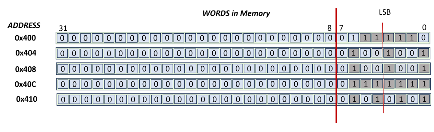
Let’s travel back in time. It’s 1989, the year Gameboy will be released in Japan and take over the world by storm. It had a small screen with B&W graphics. That is every pixel could be either on (1) or off(0). On pixels showed as black triangles (no light passing through) whereas off pixels showed as black. In an alternate timeline, you are working on a handheld console which also had B&W graphics and somehow NIOS II was the processor that it was based on. Its resolution is 5 rows by 32 columns:

So, the memory addresses 0x400 through 0x413 are mapped to the display. By making a bit 1, we expect the corresponding pixel to be black and vice versa. For this discussion we will skip over the physical realities of how this can be implemented. We are focusing on how the programmer can “paint” what they want on this screen.
Let’s start by painting a “sprite” on this screen. We will use the following assembly:
.data
.align 2
fb: .word 0x3E, 0x49, 0x7F, 0x7F,
0x55, 0x00
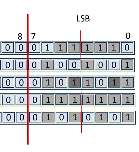
Let’see what we painted:
I hope this looks like the ghost from pacman or a little alien creature from invaders. In the above drawing, the creature is looking straight up from the screen.
Is it looking right?
For the game, we want to be able to check whether it is looking left or right. For example, when it is looking right the creature will be like this on screen (notice the two extra pixels that are on – we highlight them differently but on the actual screen it would be a pixel that is on like all others):
|
|
|
|
Alien Looking
Right |
Alien Looking Left |

OK, now let’s try to write the first useful piece of code that checks whether the creature is looking right. The pseudo-code is as follows:
V = read word from third row (address 0x408)
Make all bits of V 0, except bits 1 and 4
Is the final V 0? Then the alien is not looking right.
So, we know that NIOS II provides us with bit-wise operations where they treat the inputs as 32 element bit vectors and perform 32 2-input binary operations as in AND, OR, NOR, XOR in parallel.
So, for some input bit positions we want the output to be 0, whereas for others we want the output to be whatever the input bit is. Effectively we need a “programmable gatekeeper”. That would be the AND operation:

ANDing with 0 always results in 0, whereas ANDing with 1 allows the input value to pass through to the output. A term some people use is that we are “masking” out all bits except the bits we care about.
In our case, we want to AND with a pattern that has 1 only in bit positions 1 and 4 (assuming we counting from right starting at bit 0). In binary this is this number 00…0001 0010, and in hex (for convenience and readability by humans) it can be written as 0x12. That number (0x12) is called a “bit mask” but this is not universally adopted terminology.
Here’s the assembly:
.text
LooksRight: movia r8, fb #
base address of framebuffer
ldw r9, 8(r8) # read third row
word
andi r9, r9, 0x12 # mask out all
but bits 1 and 4
beq r9, r0, NotLookingRight
IsLookingRight:
code goes here
br AfterCode
NotLookingRight:
other code goes here
In the above code, r9 will end being 0x12 if the alien is
looking right and 0 otherwise.
Turn on the eyes as if they are looking left?
For the next useful piece of code, we would like to make the alien look left. Here we assume that the only thing we know about the alien drawing is that the pixels for looking left are at positions 2 and 5, whereas the pixels for looking right are at positions 1 and 4. That is, there could be other drawings, but all use these bits for the eyes (for example, another alien can have two more pixels for antennas, or hands or tentacles).
So we would like to keep all other pixels (bits) in row 3 as they are, and only affect the aforementioned ones. We want the pixels at positions 2 and 5 to become 1 irrespective or what they are now, and the pixels at positions 1 and 4 to be 0. The process for this is to read the word that is presently in row 3, manipulate the bits we want, and then write the new value in. So we will read the value using a load, modify it using an appropriate combination of bitwise operations, and then write the modified value using a store.
Let’s start the code
.text
LookLeftMake: movia r8,
fb # base address of framebuffer
ldw r9, 8(r8) # read third row
word
CODE
TO MODIFY R9 GOES HERE
stw r9, 8(r8)
Zeroing out bits: Let’s now discuss what the code that modifies r9 can be. We first need to zero out bits 1 and 4. The AND operation can help us here. We will use 1 for all bits except for those that we need to turn of. The mask (constant) that we need to AND r9 with is:
111…1 1110 1101
That has 0 only in bit positions 1 and 4. In hexadecimal this can be written as 0xFFFF FFED. The code is as follows:
movia r10, 0xFFFF FFFE
and r9, r9, r10
We cannot use ANDI here because we need a full 32b mask where the upper 16bs are all 1s and (please double-check with the instruction reference) ANDI accepts only a 16b immediate which it ZERO-extends to 32b. SO if we wrote ANDI r9, r9, 0xFFED we would be ANDing with 0x0000FFED and not with 0xFFFF FFED. Recall that ADD and SUB and LDW and STW also use 16b immediates, but SIGN-extend them.
Turning bits on: Next we need to turn on (set to 1) bits 2 and 5. For this we need a bit operation that either passes its input unmodified (this will be used for all other bits except bits 2 and 5) or outputs 1. The OR function can be used for this purpose:

Accordingly, we will OR with a mask that has 0s for all bits except for bits 2 and 5. For those it will have 1s. The mask is 0x24 and the code looks like this:
ori r9, r9, 0x24
And the code in its full glory is as follows:
.text
LookLeftMake: movia r8, fb # base address of framebuffer
ldw r9, 8(r8) # read third row word
movia r10, 0xFFFF FFFE
and r9, r9, r10
ori r9, r9, 0x24
stw r9, 8(r8)
Toggle the right eyes?
The next code’s purpose is to change the state of the right eyes. If they are 1 we want to make them 0 and vice versa. We could do this we if-then-else code (branches). Alternatively, we could use a “selective inverter”, that is a bit operation that we can control so that it either passes the value as is (used for all bits but the ones we want to toggle) or inverts it (used for the bits we want to toggle). We can use the XOR operation for this purpose:
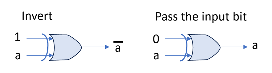
For our purpose, we will need to XOR with 0x12 for the right eyes. The code is as follows:
.text
RightEyesToggle:
movia r8, fb # base
address of framebuffer
ldw r9, 8(r8) # read third row word
xori r9, r9, 0x12
stw r9, 8(r8)
The next code’s purpose is to change the state of the right
eyes. If they are 1 we want to make them 0 and vice versa. We could do this we
if-then-else code (branches). Alternatively, we could use a “selective inverter”,
that is a bit operation that we can control so that it either passes the value
as is (used for all bits but the ones we want to toggle) or inverts it (used
for the bits we want to toggle). We can
use the XOR operation for this purpose:
It’s coming after you
Moving along, next we would like for our alien to slide on the screen. For this purpose we can use the shift or the rotate instructions. The shift instructions will make the alien disappear across the edges when we shift out of them. The rotate will make the alien appear on the other side of the screen (as done in pacman). Here we will show the code for shifting the alien by one but to the left. The code belows go through all four rows and shifts their contents by one bit to the left. It is not meant to be the most efficient way of doing this, only just a way.
.text
MoveLeft:
movia r8, fb # base
address of framebuffer
movi r9, 5 # r9 = rows
movi r10, 0 # index of
next row to process
RowProcess:
ldw r4, 0(r8) # read next row
sll r4, r4, 1 # shift bits left by 1. Bit 0 is
filled with 0.
stw r9, 0(r8) # write
back to the framebuffer
addi r10, r10, 1 # one
more row processed
addi r8, r8, 4 # pointer
to next row (each row is 4B)
blt r10, r9, RowProcess
# still rows to go?
Aftercode: