Andreas Moshovos
Fall 2007
Updated Fall 2013
Using Interrupts
Continued: Other causes of interrupts and an example of how they can be used to
emulate new or unimplemented (in hardware) instructions.
In the previous lecture we have seen how interrupts can be used to communicate with I/O devices. We noted that the interrupts mechanism has a lot more diverse applications. Interrupts can be used to detect erroneous conditions during execution such as a division by zero or a misaligned memory access. In other processors interrupts are also used to support Operating System calls (currently, NIOS II does not have support of this kind).
Emulating
non-implemented instructions
As an example of other uses of interrupts we will see how we can emulate an instruction in software. For example, the NIOS II instruction reference defines the instruction “mulxuu rC, rA, rB”. This instruction multiplies the values of registers rA and rB and writes the upper 32 bits of the result into register rC. Note that since registers are 32-bits each, multiplying them may result in a value that requires 64-bits to be represented. This instruction treats the input values as unsigned. Combined with the regular “mulu” instruction we can use “mulxuu” to do a full 32-bit x 32-bit multiplication. Not all NIOS II implementations include a hardware unit for “mulxuu”. The reason for that is that this unit is quite expensive. So some implementations opt to rely on emulation to execute this instruction.
This interrupt can be used to emulate in software instructions that are not really implemented in hardware. Once our interrupt handling routine is written, the emulated instruction can be used as if it was implemented in the CPU. For example, it used to be the case that one could get 80386 which implemented the integer subset of the x86 instruction set in hardware (80386 is Core Duo’s grand-grand-grand-grand-“father”). The x86 instruction set, however, included instructions for floating point numbers too. To get hardware for those you had to get the 80387 processor which was a co-processor that worked in tandem with 80386. If you didn’t have the 80387 you could always use interrupts to emulate these instructions in software and still run programs that used them (albeit a lot more slowly than they would run if you had 80387).
Before we emulate the instruction let’s see how it is encoded:
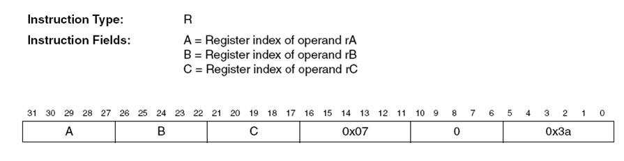
Bits 31 through 27, 26 through 22, and 21 through 17 encode the two source operands and the destination register respectively. Bits 16 through 11 should hold the value 0x7, bits 10 through 6 the value 0 and bits 5 through 0 the value 0x3a. In binary these are respectively, 000111, 00000, and 111010. So, bit 16 should be 0 and the lower 16 bits should hold the value 0011 1000 0011 1010, or 0x383a.
The interrupt handler is structured as follows:
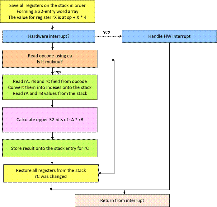
Here’s the assembly code for the interrupt handler. This code will not work when any of sp, et, or ea are used as the destination register for mulxuu.
|
.section exceptions # tell the assembler to not introduce
any additional instructions overwriting registers .set nobreak .set noat handler:
########################################### # store all registers on the stack
# forming an array of words # the value for register X is at
sp+X*4 where X a number 0...32 ########################################### # save all registers on the stack subi
sp, sp, 32 * 4 stw r0,0(sp) stw r1,4(sp) stw r2,8(sp) stw r3,12(sp) stw r4,16(sp) stw r5,20(sp) stw r6,24(sp) stw r7,28(sp) stw r8,32(sp) stw r9,36(sp) stw r10,40(sp) stw r11,44(sp) stw r12,48(sp) stw r13,52(sp) stw r14,56(sp) stw r15,60(sp) stw r16,64(sp) stw r17,68(sp) stw r18,72(sp) stw r19,76(sp) stw r20,80(sp) stw r21,84(sp) stw r22,88(sp) stw r23,92(sp) stw r24,96(sp) stw r25,100(sp) stw r26,104(sp) stw r27,108(sp) stw r28,112(sp) stw r29,116(sp) stw r30,120(sp) stw r31,124(sp) |
|
rdctl et, ctl4 #
Check that interrupt was caused by software beq et, r0, software #
if not, it's a hardware interrupt ignore HANDLE HARDWARE INTERRUPTS HERE br iEpilogue |
|
##################################################### # read the instruction opcode to test whether it is a mulxuu # ea points to the instruction ##################################################### software: stw r9, -4(ea) add r10, r9, r0 # keep a copy of the opcode andi r9, r9, 0xffff # keep just the lower 16 bits cmpeqi r11, r9,
0x383a beq r11, r0, notmulxuu srli r10, r10, 16 # shift the upper 16 bits into the lower
16 andi r11, r10, 0x1 # test bit 0 which used to be bit 17 bne r11, r0, notmulxuu
# if not zero this is not mulxuu |
|
##################################################### # Operand index calculations ##################################################### ismulxuu: # now calculate indexes into the stack for accessing # the input and output operands # treat the stack as a 32-entry array of words # we extract the 5 bit field for each operand # multiply by four because each entry is four bytes # and add the stack point which is the base of the array ##################################################### srli r10,r10,1 # keep just the upper 15 bits of the opcode # rC andi r11, r10, 0x1f # these are the 5 bits indicating rC the
destination register slli r11, r11, 2 # multiply by 4 add r11, r11, sp # add the base of the array # rB srli r10, r10, 5 andi r12, r10, 0x1f #
keep the bits for rB slli r12, r12, 2 # multiply by 4 add r12, r12, sp # add the base of the array # rA srli r10, r10, 5 andi r13, r10, 0x1f #
keep the bits for rA slli r13, r13, 2 # multiply by 4 add r13, r13, sp # add the base of the array ##################################################### # Access input registers ##################################################### # at this point: # r11 points to the entry for rC # r12 points to the entry for rB # r13 points to the entry for rA # read rA and rB into r9 and r10 respectively ##################################################### stw r9, 0(r13) stw r10, 0(r12) |
|
##################################################### # Multiplication : No need to understand how this works # end result is in r10 # I haven’t tested it much :( ##################################################### srli r4, r9, 16 # a = (v1 >> 16) & 0xffff; andi r5, r9, 0xffff # b = v1 & 0xffff; srli r6, r10, 16 # c = (v2 >> 16) & 0xffff andi r7, r10, 0xffff # d = v2 & 0xffff; mul r9, r5, r7 # LO = b * d; srli r9, r9, 16 # y = ((LO >> 16) & 0xffff) mul r10, r4, r7 # x= a * d mul r12, r5, r6 # x1 = c * b add r10, r10, r12 # x = x + x1 add r9, r9, r10 # y = y + x srli r9, r9, 16 # y = (y >> 16) & 0xffff mul r10, r4, r6 # HI = a * c add r10, r10, r9 # HI = HI + y |
|
##################################################### # write result onto the corresponding stack entry ##################################################### # store the result to the stack stw r10, 0(r11) # declare this instruction as executed addi ea, ea, 4 |
|
iEpilogue: notmulxuu:
########################################### # restore all registers from the
stack # one value has been
changed
########################################### stw r0,0(sp) stw r1,4(sp) stw r2,8(sp) stw r3,12(sp) stw r4,16(sp) stw r5,20(sp) stw r6,24(sp) stw r7,28(sp) stw r8,32(sp) stw r9,36(sp) stw r10,40(sp) stw r11,44(sp) stw r12,48(sp) stw r13,52(sp) stw r14,56(sp) stw r15,60(sp) stw r16,64(sp) stw r17,68(sp) stw r18,72(sp) stw r19,76(sp) stw r20,80(sp) stw r21,84(sp) stw r22,88(sp) stw r23,92(sp) stw r24,96(sp) stw r25,100(sp) stw r26,104(sp) stw r27,108(sp) stw r28,112(sp) stw r29,116(sp) stw r30,120(sp) stw r31,124(sp) # restore the stack addi sp, sp, 32 * 4 br idone |
|
# for hardware interrupts re-execute instruction that was
interrupted eadec: subi ea, ea, 4 idone: eret |
Here’s a piece of code that uses the new instruction
.text
.global main
main:
movhi r9, 0xffff
ori r9, r9, 0xffff
add r10, r9, r0
mulxuu r11, r9, r10