Computer Organization
Andreas Moshovos
FALL 2013
Virtual Memory
Concept
Applications when ran on a computer system need to use memory to store their instructions and data. In the systems we are using there is only one application running at a time which can access any part of the memory it desires. Let’s say now you wanted to have two applications ran at the “same” time. How can you do that? There are two issues at hand: (1) How do you run two applications when the processor can only run one instruction at a time, and (2) which application get’s to use which part of memory. Let’s first briefly talk about the first issue, which is multi-tasking. The goal of this lecture note is to discuss the mechanisms for supporting the “sharing” of main memory among multiple applications. The key mechanism for doing that is virtual memory, at the end of this note there is short description of how multi-tasking works. For the time being suffices to say that multi-tasking is done by time sharing the processor. That is one application runs for some period of time, say 100ms. Then it saves all registers in some part of memory, and then another application restores all registers from its own saved copy of register values and resumes execution, running for another 100ms. Once all applications have been given the chance to run for 100ms each, then execution returns to the first application which is allowed to execute for another 100ms. Provided that the time period allocated to each application is short, to the user it seems as if the applications are running simultaneously. However, they are not, they are just time sharing the processor.
How can multiple
applications work using just one main memory
When applications time-share the same processor, there is only one main memory. How do they get to peacefully co-exist. In the system we are using in the lab there is only one application running and it has absolute control over the whole memory. What if you wanted to have two applications time share the processor? They cannot both use the same parts of memory. We cannot have application A store its instructions starting at address 0x10 0000 while application B does the same. Somehow, we need to have them use separate parts of memory. In general any combination of applications that may ever run simultaneously on the processor would have to agree and use different addresses for their instructions and data. This could be done through a central authority that allocates chunks of memory but that solution is not really workable for many reasons. For one, each application that ever existed would have to be allocated some part of memory it only could ever use. Moreover, the system would have to have as much memory needed by all applications ever.
Even if this were possible, there would be nothing to prevent an application A accessing data or altering instructions for another application B. What if B was maintaining some financial data or was controlling a nuclear re-actor. We wouldn’t want any other random application mocking around with such data.
So, a solution is needed to allow: (1) Isolation, (2) Protection, and (3) memory usage independence across applications. Isolation refers to precluding other applications from accessing data and instructions belonging to another application. Protection is a related mechanism that controls which parts of memory and thus also devices an application and can access and what can it do with them. For example, an application could be allowed to read part of memory (that contains a buffer with network data) but may not be allowed to overwrite it, or it could be allowed to execute some code but not change it. Requirement (3) (the verbose term used is not standard and is only meant to convey the meaning) is about letting applications pick and choose where they will store their instructions and data and be allowed to do that independently of any other application. The solution to these requirements is virtual memory.
Virtual Memory
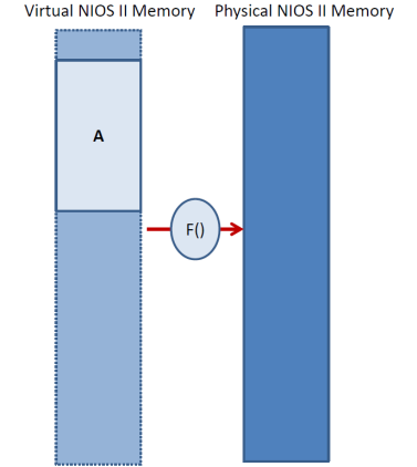
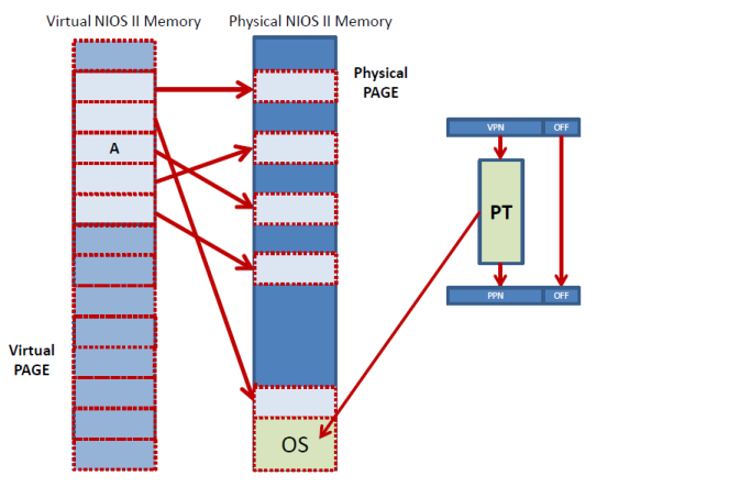
Virtual memory presents each application with the illusion that it has exclusive access to the whole memory address space. For example, in NIOS II under virtual memory each application would be given the illusion that it has access to the full 4GB address space. However, in reality each application is allowed to access its own dedicated virtual address space which at runtime gets mapped onto the actual memory space that is implemented in hardware. The latter is referred to as the physical memory space. As the figure below shows, the application accesses virtual addresses which appear to be 32-bit address as they would be on a regular NIOS II system. However, before the access is performed, a translation layer translates the virtual address into another physical memory address. For example, in NIOS II the physical addresses will also be 32-bits. This translation layer is implemented usually using a combination of hardware and software.
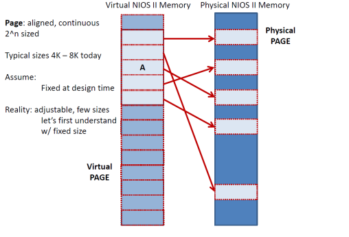
How does this mapping f() from virtual to physical addresses work? As the figure below shows the virtual and physical address space are conceptually divided into pages which are large continuous, aligned blocks that are of power two size. The typical page size today is either 4K and 8K. For the time being assume that the page size is fixed at design time and does not change. So, for the sake of this discussion assume 4KB pages. Each virtual page is mapped onto a physical page (shown by the arrows below). For example, the virtual page that starts at address 0x1 0000 and end at 0x103FF can be mapped to the physical page that starts at 0x2000 and ends at 0x23FF. The figure below shows these mappings as arrows pointing from the virtual pages to the corresponding physical pages. Since we have 4KB pages, the lower 12 bits of the address is just an offset within the page and the remaining 20 bits are the page number. For example, virtual address 0x0000 0201 belongs to page number 0x0 and is at offset 0x201. The table below gives a few more examples of virtual addresses and their corresponding virtual page numbers and offsets.
|
Virtual Address |
In Binary (offset
in bold) |
Virtual Page Number |
Offset |
|
0x12345678 |
0001
0010 0011 0100 0101 0110 0111 1000 |
0001
0010 0011 0100 0101 01 or 0x048D15 |
10
0111 1000 or 0x278 |
|
0xDAFA
BDAD |
1101
1010 1111 1010 1011 1101 1010 1101 |
1101
1010 1111 1010 1011 11 |
01 1010 1101 |
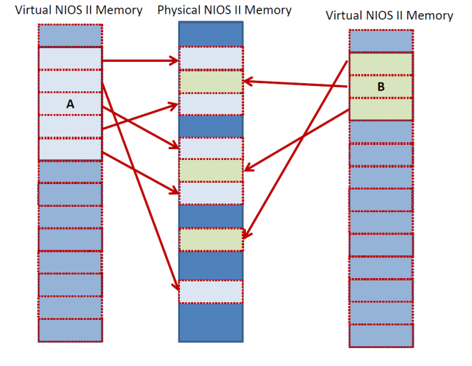
With virtual memory in place the following are possible. An application can have its virtual pages mapped to any physical pages. This way an application can use as much memory as it needs. Another application can co-exist as long as its own virtual pages are mapped to different physical addresses that are not used by any other application. Each application is free to use any addresses in its own virtual memory space. The following figure shows two applications co-existing peacefully in the same physical memory space. Application A and B never collide in physical memory, but they both access any address they want in their own virtual space:
Implementing the
Virtual to Physical Address Translation
As we discussed virtual memory works by mapping the virtual address space of an application to the physical space that exists in the machine. This mapping is done at the page number level. That is the translation mechanism translates the virtual page number that the application uses to physical pages numbers that can be used by the hardware to access memory. This is done via a page table as shown in the following figure:
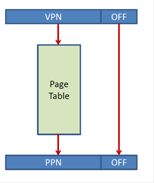
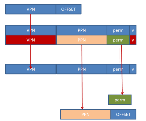
Here’s how it works: Say a NIOS II application executes a ldw r2, 0(r8) instruction and that r8 contains 0x1000. That is, the ldw would normally try to access address 0x1000. With virtual memory, this address is a virtual address which will be first translated into physical address. The 0x1000 virtual address is broken into two pages. The offset, which is the lower 12 bits ( 00…00 in this case) and the upper 20 bits which form the virtual page number VPN (0…0001 00 this case). The VPN is used to index the page table and to access an entry there. The entry contains the physical page number PPN where the VPN has been mapped to. The PPN is concatenated with the original 12 offset bits and this now becomes the physical address. This is then used to access memory. For example, the PNN might be 00…01 which would mean that the resulting physical address would be 0…0100 0000 0000, or 0x400.
For the time being assume that the physical page is just a flat table with one entry per possible VPN. For NIOS II with 4GB of memory and with 4KB pages that would mean that the page table would have 1M entries. To allow each application to have its own virtual address space a separate page table can be used per application. This way we have isolation across application. Each page table entry contains at the very least the PPN the virtual page has been mapped to. To support protection as well, typically the page table entry contains permission bits such as read, write, and execute. For example, this way an application can be allowed to just read from a page but not allowed to execute code or write to.

Page Table Entry Structure (simplified)
In addition, the page table entry can have a valid bit to support on-demand allocation of pages. That is, the mapping is initially non-existent for all pages. Once the application tries to access a page, it finds that the page table entry is invalid. An interrupt is raised in reaction and the OS then allocates an appropriate physical page and returns execution to the program. This way the program does not need to allocate all of its pages before executing. Pages are allocated as the program is touching them. This way, dynamic memory allocation can be supported as well. Otherwise, how would be allocate enough memory for all possible malloc calls the application might do?
Lifetime of Pages
When an application is first launched, the page table is empty. The application then tries to fetch its first instruction. The machine tries to translate the virtual address for that instruction into the corresponding physical address only to find that no such mapping exists – the page table entry for the page containing the instruction is empty. As a result, a page fault interrupt is raised. The OS takes over, allocates a physical memory page, updates the page table entry and copies the appropriate instructions there from secondary storage (e.g., the disk). The interrupt handler returns to the application which now retries the instruction fetch. This time, the page table entry is valid and the fetch can proceed.
Where is the Page Table
The page table itself lives in memory. Specifically, suffices to assume that the page table itself is stored in part of memory that belongs to the OS. Before launching an application the OS allocates a page table in part of the memory as shown in the following figure:
The Trouble with Page
Tables and Address Translation
The nice functionality and convenience that virtual memory provides it comes with a performance cost. Every memory access has to be first translated from the virtual space to the physical address space. This means that for every instruction fetch, and data load or store, we have to first access the page table. Since the page table itself is in memory, this means that every memory access now requires first at least one additional memory read to access the page table. Moreover, each page table access needs to access the PPN, valid bit and permission bits. These are several bytes in total (for example, we saw that for NIOS II the PPN would be 20-bits, the valid bit is one additional bit, and for read/write/execute permissions would be need another 3 bits for a total of 24 bits or 4 bytes in total). Finally, a permission check must be performed to determine whether the access is allowed or not. If the access is not allowed, a protection violation interrupt will be raised notifying the OS to take appropriate action.
If every memory access requires accessing another four bytes, we have a problem. Memory is already slow as it is, now we are making it even slower: every access will need to first do a memory read for a word, and then the actual access can proceed. To avoid having to access the page table from memory at every access modern processors implement a page table entry cache. The cache is called the Translation Look-aside Buffer (TLB). The following figure shows a fully associative TLB:
The incoming VPN is broadcast over all TLB entries which compare their VPN tag with it. If a match is found the cached PPN is produced along with the permission bits. Initially, the TLB is empty and an access will miss in the TLB and have to access the page table in memory paying an expensive price in terms of latency. However, instead of throwing away that translation info, the processor then copies that info in the TLB. If the next access happens to be on the same page, then that access will be serviced by the TLB and the access to the page table will be avoided. The TLB entries need a VPN tag since they can cache any entry from the page table. Accordingly, the TLB entry must note which page table entry it is a copy of. Since the index to the page table is the VPN, the tag need to be the VPN itself. Notice that the valid bit in the TLB is not the page table valid bit. The TLB valid bit only reports whether the entry contains a valid copy of a page table entry. Copies are made only for valid pages. The TLB must be kept coherent with the page table in memory. This is the job of the OS. The OS often invalidates TLB entries (for example, when an application terminates).
The TLB shown uses just the VPN to identify which page table entries it contains copies of. When the current running application changes, these entries will have to be evicted since the incoming application uses its own virtual memory. For example, both can be using virtual page 0x1000, however, the virtual page 0x1000 for application A is not the same as the virtual page for application B. In the TLB shown there is no way to distinguish between the two since the TLB does not identify which page table it copied the entries from. TLB entry invalidation can be done by the OS prior to context switching in the new application. Alternatively, a context tag can be added to identify which application the TLB entries are for.
Since the TLB is a cache, most of the concepts we discussed about cache management apply here with minor modification. Think of the TLB as a cache where the application does only reads and the OS does the writes. Typical TLB organizations today have about 64-128 entries organized as fully-associative.
How big does the
physical memory need to be
In our discussion thus far, we assumed that the virtual and the physical memory spaces are of the same size. This does not need to be so. The physical address space can be of different size by adjusting the PPN bit length. For example, we can translate the 32-bit virtual address space of NIOS II to a say 40-bit physical address space, or even to a smaller physical address of say 20 bits. Why would we want to do that? The latter would allow us to run applications that use 4GB on a physical implementation that only has 1MB. How can this be done? Via the help of secondary storage. The page table can be extended to identify pages that have been swapped out. As before, a page is initially allocated in physical memory. Assume now that all physical pages have been occupied and an application tries to access a never accessed before virtual page. The OS needs to allocate a new physical page for that. However, all are taken. The OS picks a victim page and writes its contents to a secondary storage device (for example, a hard drive). The page table entry for that page is marked indicating that the page is no longer in memory and is instead in secondary storage. The freed physical page can now be used for the newly accessed virtual page. If the application tries, at a later time, to access the page that was swapped out, the OS can pick another victim, swap that out, and bring the desired page back in. This way an application can access many more pages that the physical memory can hold at any given point of time. Of course, there is a performance penalty that is paid for swapping pages in and out of secondary storage. But at least the application runs. Whenever swapping activity becomes severe, we have memory thrashing which is really detrimental to performance as most time is spent copying pages and in out from physical memory than actually executing programs.
Multi-Level Page
Tables
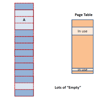
So far, we have a assumed a
monolithic page table. That is once an application is launched all page table
entries are allocated. For NIOS II that would mean that a 4M entry page table
would need to be allocated for each application. This is wasteful since the
application would rarely use all 4G of its virtual memory space. Moreover, if
there was a 64-bit address space NIOS II the page table would need to have 4G
entries. So, in practice we see that as the following figure shows,
applications typically use only part of their memory space and, as a result,
only part of their page table:
To avoid allocating all the page table for every application, systems often use hierarchical page tables. Specifically, the page table itself is broken conceptually into large chunks as shown below:
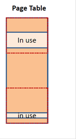
The figure shows that the table has been divided into three chunks with only two of them being actively used. Then, instead of allocating memory for all of the chunks, memory is allocated on demand only for the chunks that have valid entries. If we chose to use a number of chunks that is a power of two, then part of the VPN can uniquely identify each chunk and the remaining part identifies an offset for the entry within the chunk. The following figure shows a generic two-level page table organization:
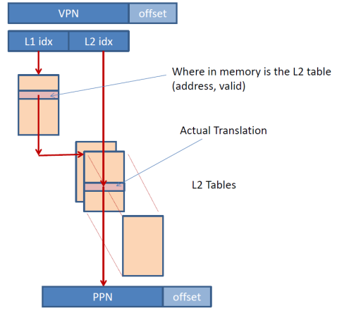
The VPN is broken (conceptually) into two parts, L1 idx and L2 idx. The L2 idx is an offset into one page table chunk. The L1 idx identifies which chunk that is. A first level table indexed by L1 idx identifies where in memory each L2 chunk starts. The whole level one table is allocated but entries are populated with valid base addresses only for the L2 chunks that have been allocated. This way the page table needs to allocate entries at the L2 chunk granularity and only for the L2 chunks that have valid page table entries. The L2 tables contain the actual page table entries.
For example, assume that the L1 idx is 12 bits wide. Then the L2 idx would be 8 bits wide for NIOS II and 4KB pages since the VPN is 20 bits wide. The L1 table would contain 4K entries. Each of these entries would contain an address identifying where in memory is the corresponding L2 chunk allocated at. It would also need a valid bit indicating whether the L2 chunk is allocated (the NULL value could be used instead). The L2 chunks would each contain 256 page table entries. Only the L2 chunks that have valid entries would need to be allocated and this can be done on demand.
For example, say that an application has only two virtual pages that are currently mapped to physical pages, and say these are VPN 0x3 and VPN 0x1000 that are mapped to PPN 0x2000 and 0x130 respectively. For the example 2-level table organization discussed thus far, the level 1 table would contain 256 entries. Each entry would have 4 bytes (we assume that value 0 means that the chunk is not allocated) containing an address where the corresponding L2 chunk is allocated at. Let’s see how the VPNs would be translated here. First we need to find which L1 entry each VPN maps to. Since the L2 chunks contain 256 entries each, the last 8 bits of each VPN are an offset within an L2 chunk. The remaining upper 12 bits are the L1 table index. So, it follows that VPN 0x3 maps to entry 0 of the L1 table while VPN 0x1000 maps to entry 0x10. Those two entries would contain non-zero 32-bit addresses. Entry 0 would point to an L2 chunk containing 256 page table entries and entry 0x10 would point to another. All other L1 table entries will be invalid (containing 0 in our example). For the L2 chunk for entry 0, all entries would be invalid except for the entry at index 0x3 which would contain the translation for VPN 0x3 reporting that it is mapped to PPN 0x2000. For the chunk pointed to by L1 entry 0x10, only entry 0 would contain valid entry which would point to PPN 0x130.
Multi-tasking
How can two applications run at the same time on a single processor? The short answer is that they can’t. However, from our everyday experience with computing devices we do know that multiple applications do run at the same time. How is this done? It’s done by time multiplexing. That is, given application A and B. First application A is allowed to run say for 100ms, and then application B is allowed to run for 100ms, and then we return back to application A let it run for another 100ms, and so and so forth. So, at any given point of time, only one application is running. It is allowed to make some forward progress for some amount of time and then, another application is allowed to do that same. How is this implemented? First a hardware timer is used to trigger interrupts every say 100ms. Then the application is allowed to run. Once the timer raises an interrupt, the interrupt handler switches execution the next application that needs to run. But what happens to registers or memory? If we switch to another application what will happen to register values? Moreover, how do we know which application to switch next, where it is in memory, etc.? This is the job of the Operating System (OS). The operating system is a software program that keeps track of which applications are running and orchestrates their execution. When you first boot a computing system, the operating system is loaded from some persistent storage device (ROM or disk drive). Once the operating system is up, it provides the user with the capability of launching additional applications. The user has to specify the location of an image of the program’s instructions, initial data (which can be again in some persistent storage) and the starting PC value. The OS copies this image in memory and then launches the application. The OS maintains a list of all applications that are currently loaded in memory and active and then using the timer interrupts orchestrates their execution.
Let’s take things from the beginning. The user asks to execute a program whose instructions and data has been already loaded in some part of memory. The user specifies the starting PC value. The OS sets up the timer to 100ms and then changes the PC to the user provided value. The application runs and 100ms in the future the timer triggers an interrupt. The interrupt handler now saves all necessary state and switches to another application from the list of available applications. What is the state that needs to be saved? This includes all mutable registers. For NIOS II that would all general purpose registers and the current PC value. So, the OS preserves all register values in some table that has space reserved for each application and then switches to another application.