


| Main | Assembly Programming | Input/Output | Memory | Computer Architecture | Advanced Topics |
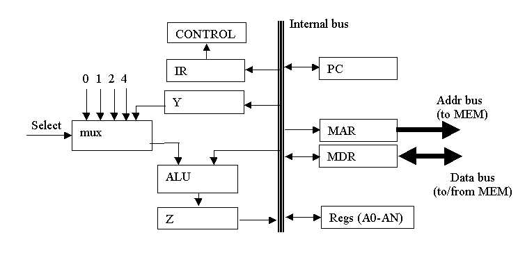
Consider the architecture as shown and the following instruction:
link a6, #-8
| Step | Control Signals | Comment |
|---|---|---|
| Step 1 | PCout, MARin, READ, select 2, ALUadd, Zin,WMFC | Fetch inst, inc PC |
| Step 2 | Zout, PCin | Fetch & inc |
| Step 3 | WMFC, MDRout, IRin | Fetch & inc |
| Step 4 | A7out, select 2, ALUsub, Zin | Z<-[a7]-2 |
| Step 5 | Zout, a7in, MARin | A7<-[Z] |
| Step 6 | A6out, MDRin, WRITE | [A7]<-[A6] |
| Step 7 | A7out, A6in, Yin | [A6]<-[A7];Y<-A7 |
| Step 8 | WMFC, PCout, MARin, READ, select 2, ALUadd, Zin | Z<-[[PC]] (fetch #-8, inc PC) |
| Step 9 | Zout, PCin | Inc PC |
| Step 10 | WMFC MDRout, select Y, ALUadd, A7in, END | A7<-[Y]+(#-8) |