

| Main | Assembly Programming | Input/Output | Memory | Computer Architecture | Advanced Topics |
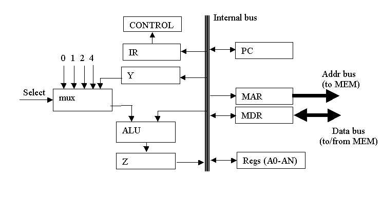
Consider the architecture as shown and the following instruction:
link a6, #-8
sp <- [sp] - 2;
[sp] <- [a6];
a6 <- [sp];
sp <- [sp] - 8;


Consider the architecture as shown and the following instruction:
link a6, #-8
Local variables.
Consider the architecture as shown and the following instruction:
link a6, #-8
| Step | Control Signals | Comment |
|---|---|---|
| Step 1 | PCout, MARin, READ, select 2, ALUadd, Zin,WMFC | Fetch inst, inc PC |
| Step 2 | Zout, PCin | Fetch & inc |
| Step 3 | WMFC, MDRout, IRin | Fetch & inc |
| Step 4 | A7out, select 2, ALUsub, Zin | Z<-[a7]-2 |
| Step 5 | Zout, a7in, MARin | A7<-[Z] |
| Step 6 | A6out, MDRin, WRITE | [A7]<-[A6] |
| Step 7 | A7out, A6in, Yin | [A6]<-[A7];Y<-A7 |
| Step 8 | WMFC, PCout, MARin, READ, select 2, ALUadd, Zin | Z<-[[PC]] (fetch #-8, inc PC) |
| Step 9 | Zout, PCin | Inc PC |
| Step 10 | WMFC MDRout, select Y, ALUadd, A7in, END | A7<-[Y]+(#-8) |
This question assumes the machine architecture at the right. Note the stack pointer register, SP, is not part of the register file. SEL is a multiplexor used to select one of the inputs to the ALU.
Assume memory addresses require only one memory cycle to fetch or store (unlike the 68000).
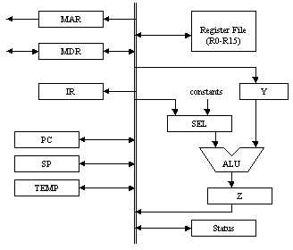
Show the machine code control sequence of the RTE (return from exception/interrupt) instruction as in the 68000 showing the register transfers at each step that implements the instruction. Include the instruction fetch sequence.
This question assumes the machine architecture at the right. Note the stack pointer register, SP, is not part of the register file. SEL is a multiplexor used to select one of the inputs to the ALU.
Assume memory addresses require only one memory cycle to fetch or store (unlike the 68000).
Show the machine code control sequence of an instruction that will set a block of from 1 to 127 memory locations to zero. The size of the block is in R0 and the address of the block is in R1. Assume the instruction fetch sequence is the same as in Question 4 and start with the next step. R0 and R1 can change in the execution of the sequence.
Write a 68000 subroutine that sets a block of memory locations to zero where the size of the block (1 to 127) is in register d0 and the address of the block is in register a1. The register values can change in the subroutine.
Loop 	Moveq.b	#0,(a1)+
	dec.b 	d0
	bne 	Loop
The comment has been made that implementation of application-specific instructions in a processor can speed up an application by 20% to 1000%. Show how your results might support this comment based on analyses of your answers to Question 5 and Question 6.
The implementation of the instructions for the 68000 loop would be longer in machine code control sequences and the fetching of the instructions would take far more time.
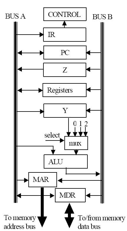 Consider the two-bus architecture shown, and the following instruction.
add.w d5,(a3)+Give the register transfer notation for each of the two parts of this instruction (assume that a word is 2 bytes)
[a3]<-[[a3]]+d5
a3<-[a3]+2
Consider the two-bus architecture shown, and the following instruction.
add.w d5,(a3)+Give the steps and control signals for implementing the instruction in the table. Use ONLY the following control signals:
| Step 1 | |
| Step 2 | |
| Step 3 | |
| Step 4 | |
| Step 5 | |
| Step 6 | |
| Step 7 | |
| Step 8 | |
| Step 9 | |
| Step 10 |
| Step 1 | WMFC, PCout, MARinA, READ, select 2, ALUadd, PCinB |
| Step 2 | WMFC, MDRout, IRin |
| Step 3 | a3out, MARinA, READ, select 2, ALUadd, a3inB |
| Step 4 | d5out, YinA |
| Step 5 | WMFC, select Y, MDRout, ALUadd, MDRinB, WRITE, END |